
A probe sized for your tank
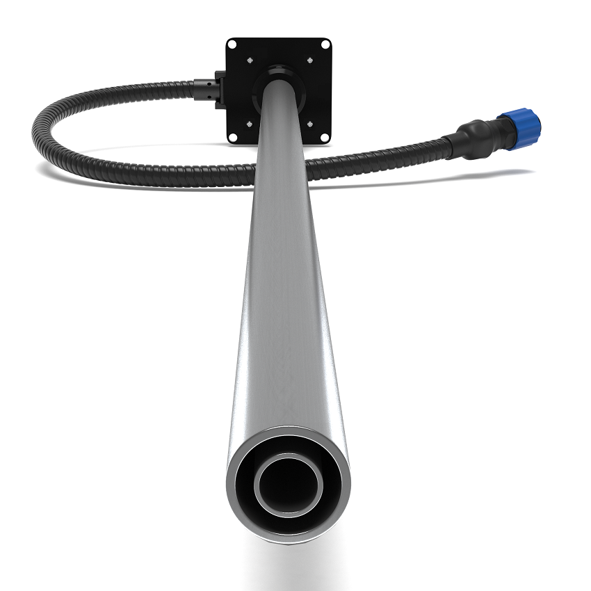
Cut the measuring probe to the required working length using the model’s installation guide.
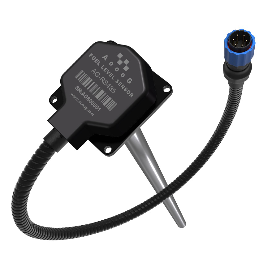
RS485 DIGITAL FUEL LEVEL SENSOR
Bring digital fuel level data into a compatible RS485 tracking or monitoring system.
For non-conductive fuels. Confirm fuel, tank and device compatibility before ordering.
PRODUCT OVERVIEW
Cut the measuring probe to the required working length using the model’s installation guide.
Set empty and full reference points with a Portable Configurator after preparing the probe.
Match the selected output to the tracker or controller, then verify readings through your system.
TECHNICAL DATA
Values follow the technical table in the 2025 wired sensor user guide. Confirm the applicable hardware revision when ordering.
Open source datasheet ↗| Output | RS485 digital |
|---|---|
| Power | 12–30 V DC |
| Measurement error | ±1% |
| Protection | IP67 |
| Maximum current | 20 mA |
| Resolution | Less than 1 mm |
| Probe length | 700 / 1000 mm; additional lengths up to 3000 mm |
| Operating temperature | −40 to +85 °C |
| Output interval | 1 second |
| Configuration | External Portable Configurator |
| Baud rates | 2400, 4800, 9600, 19200, 38400, 57600, 115200 bit/s |
| Default baud rate | 9600 bit/s |
INSTALLATION & SETUP
Use the full manual for installation. The steps below explain the workflow; dimensions and mounting allowances depend on the model and accessories.
Measure the tank and choose a position close to its geometric centre, with room for the probe and mounting hardware.
Use the specified working length and model-specific clearance. Keep metal shavings out of the measuring tube and fit the supplied filter and accessories.
Use the Portable Configurator to set empty and full reference points with the intended fuel. Verify the settings before connecting to the monitoring equipment.
Fit the gasket, seal and secure the sensor as instructed. Check the signal and tank calibration in the connected system.
| Wire colour | Function |
|---|---|
| Red | Positive supply: 12–30 V DC |
| Black | GND / negative supply |
| White | A+ |
| Yellow | B− |
Use the fuse protection specified in the manual. Check the wiring against the supplied sensor revision before applying power.
PRODUCT RESOURCES
Review the specifications, prepare the installation and connect the sensor to your application.
COMMON QUESTIONS
No. These capacitive fuel sensors are intended for non-conductive liquids. Water and other conductive liquids are not suitable.
Level and volume are different measurements. The monitoring system needs the correct data format and tank calibration to convert readings into volume for your tank.
Yes. Follow the wired user guide for the cutting allowance and mounting arrangement, keep the probe free of debris and complete empty/full calibration after preparation.
Your device needs a rs485 interface and support for the sensor output or protocol. Send us the tracker model to confirm compatibility before ordering.
LET’S FIND THE RIGHT FIT
Tell us the fuel type, tank depth and tracker interface.